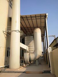
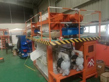
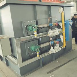
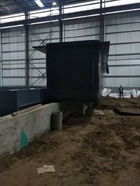
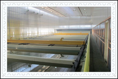
This galvanizing plant is designed so that pipes can be dipped into kettle and then be withdrawn to inner-blowing station automatically.
Star wheel type dipping device is used for pipe dipping. It can help to adjust the dipping time flexibly by using different running program.
Long lancer plug inner blowing technology by using hot compressed air is used for pipe above 1”(including 1”) . The usage of this technology results in improvement on quality of inner blowing, saving steam consumption and reducing generation amount of zinc powder.
Carefully designed zinc dust collecting system can reduce zinc consumption and help to improve operation safety of the dust filter.
- Main Technical specification
Nominal bore: Min. 1/2” – Max. 6”
Wall thickness: Min. 1.5mm – Max. 4.5 mm
Pipe length:5-6m(1/2”,3/4”) 4-6m(1”-6”)
Some kinds of squire and rectangular pipes can be treated by this line. But the line should be restricted within 2 pipes , the ratio of long and short side should be restricted within 1.5 and the min. bore dimension of pipe must be larger than 25mm.
square pipe 20*20mm;25*25mm;30*30mm;40*40mm,50*50mm;60*60mm;75*75mm;80*80mm;90*90mm;100*100mm;120*120mm;127*127mm
rectangular pipe
13*26mm;20*40mm;25*50mm;30*60mm;40*80mm;50*100mm;60*120mm;70*140mm;80*160mm;50.8*101.6mm
Dry type galvanizing system;
Pipe OD under 1-1/2”(including 1-1/2”) are processed with quadruple line way;
Pipe OD 2”-4” (including 4”) are processed with double line way.
Pipe OD 5”and 6” are processed with single line way.
Outside of pipe: By Compressed Air with outer blowing
Inside of pipe: Pipe OD 1/2”and 3/4” By Over-heated Steam inner blowing nozzle.
For pipe’s OD above 1”(including 1”) lancer plug inner blowing technique is adopted for improving the inner coating quality ,saving steam consumption and lessening the generation of zinc powder .
- For gas and water service
- For general structure purpose
B.S 1387 Light and Medium Series, DIN 2441 etc.
The metric system of measurement shall be applied.
Power Supply: By City Supply
Primary Source: 380V±5%, 50HZ , 3 phase ,Control Circuit Source: 220V ,50HZ , Single phase ,24V D,C,
Transformer for control circuit and solenoid coil shall be prepared by the seller.
General Capacity: abt. 260KW (Whole plant ; including auxiliary Equipment )
Pressure: 0.6Mpa (min. 0.5Mpa at the utility point)
Consumption: 30Nm3/h
Consumption: at full capacity: approx. 1,900,000 Kcal/hr
Natural gas 230Nm3/hr(combustion value of natural gas:8500Kcal/litre)
At idle operation: approx. 200,000 Kcal/hr
Natural gas:24nm3/hr
The pressure of gas before burners: max. 0.4Mpa
- Steam (over-heated or dry steam)
Pressure: 1.25Mpa (Min. 1.0Mpa at utility point)
Temperature: 275°C
- Zinc coating: approx. 500 g/m2 ,.By shortening dipping time the zinc coating can be reduced around 300 g/m2
- Ambient temperature : Not less than 10°C
- Production process:
The steel pipes are successively acid pickled, double flux coating and dried. And then dried pipes are immersed into zinc bath by dipping star wheel.
Production flow chart from black steel pipe to galvanized pipe is as follows: (Black steel pipe)

- Production Capacity (Example)
The following table shows examples of the production rates for each size of B.S. Medium pipes, under the favorable conditions.
| Nominal Size |
Weight of Pipe
|
Production Capacity
|
| In |
kg/m |
Kg/6.0m |
pcs./hr.approx. |
kgs/hr.approx. |
| 1/2″ |
1.22 |
7.32 |
1776 |
13000 |
| 3/4″ |
1.58 |
9.48 |
1688 |
16000 |
| 1″ |
2.44 |
4.64 |
1092 |
16000 |
| 1-1/4″ |
3.14 |
18.84 |
850 |
16000 |
| 1-1/2″ |
3.61 |
21.65 |
522 |
16000 |
| 2″ |
5.1 |
30.6 |
260 |
16000 |
| 3″ |
6.51 |
39.06 |
410 |
16000 |
| 4″ |
12.1 |
72.6 |
220 |
16000 |
| 5” |
15.03 |
90.2 |
178 |
16000 |
| 6” |
17.82 |
106.9 |
150 |
16000 |
Note :
(1) The Capacity is limited within 16000 kg/hr which is based on heating capacity of the kettle.
(2) Tube length is 6m.
(3) Above figures are based upon 100% working efficiency.
(4) Dipping time is a very big factor of the production rate when heavy coating is required. Dipping time to get necessary coating weight varies mainly according to the chemical composition of the pipes when operating conditions are the same. Production rate of those pipes which need longer dipping time will become lower.
(5) Straightness The bending of pipes shall be small as much as possible. Pipes with big bending can not be processed smoothly in this plant.
It is recommended that the bending of pipes should be less than 5mm/6m.
- Pre-treatment Equipment (batch cleaning system)
A bundle of pipes weighting usually about 3 tons is successively cleaned
in the acid pickling,1st fluxing and 2nd fluxing tanks by using over head travel crane.
No water rinsing technology is adopted for saving water consumption and easing the environment pollution.
After pickling the pipes are dipped in 1st fluxing tank (dirty) and then dipped into 2nd fluxing tank(clean). The fluxing solution of 1st and 2nd fluxing tank are connected together becoming a circulating treatment system. The flow rate of circulating system is 3 m3/h.The FeCl2 content in 1st fluxing tank will be controlled around 10g per litter and the FeCl2 content of solution after regenerating treatment will be controlled below 0.5g per litter. This clean solution will be pumped into 2nd fluxing tank (clean) and the FeCl2 content in 2nd fluxing tank will be controlled with 1g per litter. The solution will be pumped continuously into 1st fluxing tank (dirty) and then pumped to regeneration station. So that after 2nd fluxing the solution sticking to pipe’s surface will be very clean. Zinc dregs generating in kettle and zinc consumption will be reduced.
It’s recommended do not use degreasing procedure in this system by using no oil pipe’s ERW line. Other wise you have to adopt measure for treating waste degreasing solution and rinsing water.
The pretreatment equipment consists of following items
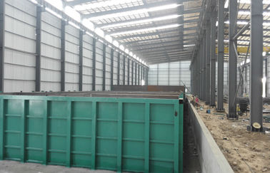
- Six sets of acid pickling tank (Drawing supply)
Dimensions : 8000(L)×1600(D)×1500(W) mm
Material : Glass fiber with mild steel structure.
- Two set of Fluxing Tank (Drawing supply)
- Flatcar for carrying pipes bundle into/out enclosed room surrounding pretreatment area. 2 sets
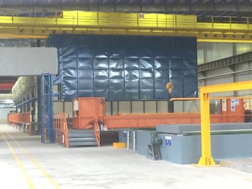
- Enclosed room surrounding pretreatment area. 30mX12mX7m
- Drying furnace
After being fluxed, the pipes are transported and dried in the drying furnace which is heated by exhaust gas of the galvanizing furnace. It consists of the following items:
- One set of the feeding table.
Material: steel structure
- One set of transmitting chain device
- Three transmitting chains
(2) One set of drive unit with gear-motor 4KW,which runs step-by-step.
(1) Furnace (with cast iron heat radiation plates) Dimensions : 8500(L)×9124(W) mm
(2) One set of steel pipe heat-exchanger for hot air blowing dry system.
(3) One set of stainless steel heat exchanger for hot compressed air used by inner blowing.
(4) One set of hearth covering plate (steel structure with heat-insulation material)
(5) One set of hot air circulating and blowing system
Hot air circulating fan capacity: 6660 NM3/hr
Temperature: abt. 150°C
Note: concrete foundation, red bricks and labor force are of buyer’ supply. 1 engineer and 3 skill workers will work for furnace construction on site.
The pre-treated and dried pipes roll down from drying furnace two by two(or four) and get into the pocket space of the dipping star wheel.
As the dipping star wheel rotate step by step, the pipes are immerged into the zinc bath (zinc bath temperature shall be 445°C- 455°C) and finally rotate to the outlet position .Then the pipes are kicked off by a pneumatic device and fall down onto the receiving racks which are installed in the kettle. Then the pipe lifting hook activates and a press plate mounted on hook presses down at the same time. With this function four pipes will be orderly distributed on receiving edge of hook and avoiding pipes to be engaged together. Then pipe(s) will be lifted by the lifting hooks and properly go through the separating plate and attached to grooves of the magnetic rollers, which are set above the zinc bath.
As the magnetic rollers are driven by a frequency conversion motor ,pipe is withdrawn up by rollers from the kettle. On the way of the withdrawing unit, the excess zinc of the outside of the pipe is wiped off by the outer-blowing device with compressed-air, for getting better wiping effect, different size of blowing nozzles are used to match different size of pipes and the pressure of blowing compress air can be adjusted by a pressure adjust valve.
When pipe reaches the top of the withdrawing rollers it is shifted to the inner-blowing station by step-walk beam. The excess zinc of the inside of the pipe is wiped off by Explosion-blowing with over-heated steam (1/2”and 3/4”) or long lancer plug with hot compressed air. Long lancer plug inner blowing method is better than nozzle method which can save steam consumption, improving quality of inner blowing and reduce generating quantity of zinc powder. But for small pipes (1//2 or 3/4”) if the pipe’s inner bore without getting deburring treatment or the weld bur is not controlled well. The long lance plug inner blowing will become very difficult. And customer can choice one according to your condition.
After inner blowing, the pipe is transferred to a cradle beam and then transferred into the quenching tank.
The system consists of following items :
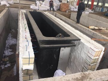
(1) Galvanizing furnace
(2) Auxiliary devices for galvanizing furnace.
Note: The concrete foundation, red bricks and labor force are of buyer’s supply, 1 engineer and 3 skill workers will work for furnace construction on site.
Dimension : 1800(W)×2910(D)×8000(L)×60(T) mm (inside effective dimens.)
Weight:37 tons .
Body material: low carbon low silicon steel (Chinese steel special for galvanizing).
Upper part with welded flat steel frame. Round corners
Ultrasonically tested, free of inclusion, impurities, blowhole etc.
- Automatic combustion System
(1) 6 Pulse Burners And Auxiliary Devices for automatic combustion
(2) Two sets of Hot Flame recirculation fans
Capacity : 27648 NM3/hr
Motor : 7.5KW
Pressure : 96 mm(H20), 20°C
Working temperature : 500~800°C
(the material for propeller is hi-temperature alloy)
If temperature of flame is lower than 500°C the fans must work in low speed to avoid motor from over load.
(3) Two sets of installation base frame for fixing burners and recirculation fan.
Material : Steel structure
(4) Combustion air fan
Capacity : 4500 NM3/hour
Motor : 18.5 KW/2p
Pressure : 9000 mm(H20), 20°C
(5) Automatic igniting and flameout monitoring system.
(6) Two thermo-couples installed in kettle for monitoring temperature of zinc melt in the kettle and two others installed in the furnace for monitoring the temperature of flame in the furnace hearth.
(1) 1 set of dipping star wheel unit consisted of 4 star wheels,1 shaft,4 supporters and driving system with AC motor N=5.5Kw , step running mode.
(2) Four racks.
(3) Machine frame
(4) One set of lifting device consists of one hook and one rotatable pressing plate, pneumatic drive
(5) One set of inlet immerging press device ,pneumatic driving.
(6) One set of outlet kick-out device, pneumatic driving.
(7) Five sets of permanent magnetic roller with driving device
AC converter motor N= 5.5 KW.
V=24-72m/min
Positioning Device of magnetic rollers (up-n-down adjust),
All parts immerged in zinc bath are of special low carbon low silicon steel material
(8) Outer Blowing device
26 sets of outer blowing rings for all sizes (from 1/2” ~ 6”)
(9) 10 sets of pipe separating plate.
(10) One set frame work for mounting magnetic rollers and its driving device.
- Withdrawing unit and inner blowing station.
(1) One set of frame work
(2) One set of roller bank Draw-out angle: 13°
(3) 5 sets of permanent magnetic roller and 5 sets of non-magnetic roller
(4) One set of driving unit for 10 rollers
Draw-out speed: 20~60 m/min (infinite-variable speed).
Drive motor: AC converter motor N=5.5 KW
(5) One set of inner-blowing station, Pneumatic drive.
For pipes OD under 1” the inner blowing is carried out by nozzles with overheat steam.
For pipes OD above 1”(including 1”) the inner blowing is carried by lancer plug with hot compressed air.
8 inner-blowing nozzles (from 1/2” ~ 3/4”)
16 lancer plug blowers(from 1”~6”)
All blowers for square pipe and rectangular pipe
As the pipe’s(1/2”,3/4”) length should cover from 5m to 6m, the stroke of inner blowing nozzle must enlarge to 800mm.
(6) Carrier and rail for inner blowing lancer and driving system
(7) One set of step-walk beam with magnetic plate,pneumatic drive unit. Motor : 2 cylinder Φ160×400 for up and down movement and 3 cylidersΦ100×800 transverse movement.
(8) Three sets of lifter driven by motors for lowering pipes from incline position for inner blowing to horizontal position. Rack and pinion, ball linear guide, ACmotor N=1.1Kw altogether 3 sets are used.
(9) One zinc dust collecting box with pneumatic enclosing door to decrease noise and zinc powder leaking.
After being cooled down in the free air for a certain time, the galvanized pipes are dipped into 70℃~ 80℃ water by cradle beam. And then the quenched pipes are taken out of the quenching tank by lifting device onto the inspection table.
Dimensions : 8500(L)×2450(W)×1500(H) mm
Type : Chain conveyor , step driving Gear motor with brake : 7.5 KW
(1) Pump (100m3/h) 3 sets
(2) Cooling tower (450,000 Kcal/h) 1 set (water pits and piping supply by buyer)
- Chain conveyor Inspection table (include water-blowing device)
Dimensions: 8500(L)×5000(W) mm
AC motor:4Kw
3 sets of displacing machine for putting pipes to 1st four groove roller conveyors.
After being quenched, the pipes are lifted onto the inspection table and then transferred onto the roller table for passivation.
- 1 sets of 4 groove roller
- Driving unit.
Individual driving,Motor: 11×0.35KW
Speed : 72 m/min
- Passivation station(stainless steel material)
- Drying chain skid with steam pipe heat exchanger and two group of displacing machine,one for inletting from 1# roller conveyor to drying skid,the other one for outletting for skid to 2# roller conveyors.(heat ex-changer and steel structure are made by buyer according drawing supplied by Fortune Machinery) (chain conveyors and displacing machine are supplied by Fortune Machinery)
- Second roller table for ink-printing
(1) 11 sets of 4 groove roller, 4 sets of them within printing area are magnetic for stabilizing pipes during printing.
(2) Driving unit.
Individual driving,Motor: 11×0.35KW
Speed : 72 m/min
- Computerized dot matrix Printing machine 4 sets.
- Fully automatic Packing station
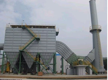
- Zinc Dust Collecting Device
Zinc dust formed by inner-blowing is collected by a zinc dust filter.
It consists of the following items :
Type : Bag filter
Filter Area : 200 M2
Control: P.L.C.
Material : Mild steel
Casing bag : Tetron needle felt
Temperature and pressure difference monitoring sensors.
Capacity: 18000 NM3
Pressure: 307 mm (H2O)
- Ventilation Fan for Warming Up Filter
Capacity: 2634 NM3
Pressure: 247 Pa
Area : 1 M2 Medium: Steam Temperature of Warm Air: 80℃
- Duct System
- Bag filter for zinc fume above kettle.
- Filter
Type : Bag filter, Filter Area : 600 M2, Control: P.L.C.
Material : Mild steel, Casing bag : Tetron needle felt
pressure difference monitoring .
- Suction fan
- Capacity: 43000 NM3, Pressure: 200 mm (H2O), N=27KW
- Duct system
- Auxiliary Equipment
- Two sets of zinc pump
- Motor: 5.5 KW
- One set of zinc dregs grab bucket
- Extraction System For Waste Fume Of Galvanizing Furnace
(1) Duct: Material: Steel structure
(2) Chimney Material: Steel structure
(3) Fan
Capacity: 3160 NM3/hr
Pressure: 106 mm(H2O)
Motor: 2.2 KW
- Electrical control system
The galvanizing plant shall be designed to make automatic control. The system consists of the followings:
- 3 sets of power supply panel.
- One set of main P.L.C. control panel
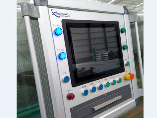
- One set of main control desk
- One set of control stall for post-treatment section
(1) steam Boiler 1 se
Capacity: 3 tons/hour
Pressure: 1.25Mpa
Temperature 275oC
(2) Air compressor 4 sets
Q=13.3Nm3/min
P=0.8Mpa
N=75Kw
- Remarks for the technical proposal
- All electrical components and motors are Schneider brand;
Converters used for important machine such as dipping machine, inner blowing carriage withdrawing magnetic rollers are of Siemens brand. Other no important usages just for lagre fans soft starting are of Chinese top brand.
- Combustion system is automatically operated;
- Piping and cabling engineering supervision;
- Installation supervision.
- Buyer’s supply:
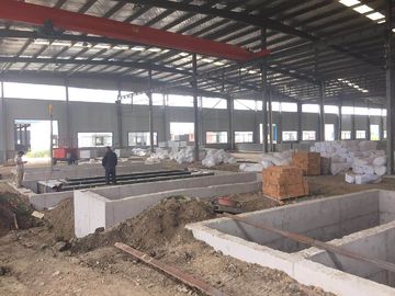
- House building;
- All machine foundation construction;
- Foundation for galvanizing furnace;
- Foundation for dry furnace;
- Concrete engineering for all floor, piping ditch, cabling ditch waste acid discharging ditch, waste acid collect pit etc. ;
- Supply of red bricks and cement for furnaces;
- Cabling and piping;
- Water pits of water cooling system for quenching tank.
- Fluxing solution collecting pit for circulating( Anti-acid coating 25m2).
- Waste acid collecting pit for treating.( Anti-acid coating 50m2)
- Diluents Acid collecting pit ( Anti-acid coating 50m2)
- Delivery terms

 Your message must be between 20-3,000 characters!
 Please check your E-mail!
  Your message must be between 20-3,000 characters!
 Please check your E-mail!
