1. Customer requirements:
2. Design principles:
Energy saving, environmental protection; technology leadership; reliable quality, cost-effective
3. Key technologies
3.1 High speed pulse heating, uniform heating, high thermal efficiency, extend the life of zinc tank.
3.2 Heating control system, the whole process of real-time data monitoring, fault diagnosis, alarm.
3.3 Use acid concentration testing equipment, can be monitored at any time to the state of acid , in order to adjust the production rhythm
3.4 Industrial waste gas closed collection, centralized treatment, meet the standards requirements (no overflow).
3.5 Use the new process, eliminating the need of water washing, reduce investment and operating costs.
3.6 The use of zinc dust collector, dust removal efficiency, easy maintenance, small size (Option)
4. Electricity, water and gas requirements
4.2 Water 0.01 cubic meters / ton, water supply pressure of not less than 0.2 Mpa
4.3 Production of water for pH =6.5 ~ 8 of tap water, river water or well water can be;
4.4 Compressed air: air pressure 0.5Mp/cm2, gas supply 3m3/min.
5. Process and workshop layout
5.1 Process layout
5.2Main production line
The equipment mainly consists of degreasing tank, acid tank, flux tank, galvanizing tank, cooling tank, passivation tank, Galvanizing tank heating and control system, Ring type crane, acid fume collection and treatment system, fixed zinc smoke collecting and treatment equipment(option) , Remove Fe from flux equipment, flux heating system(using flue waste heat),water cooling system, etc
Tank dimension:
Degreasing tank 7.0m×1.3×2.2m×1piece
Acid pickling tank 14.0m×1.3×2.2m×3piece
Flux tank 7.5m×1.3×2.2m×1piece
Water cooling tank 7.0m×1.3×2.5m×1piece
passivation tank 7.0m×1.3×2.5m×1piece
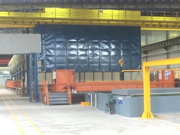
Acid fume closed room 61.0m×3.8×6.5m

• Work out reasonable investment scheme, selecting rational model unit.
• Provide free equipment layout, factory planning for you.
• Provide free equipment foundation and drawing. If necessary, offer technical guidance on-site for equipment
• Foundation construction.
• Provide equipment installation and commissioning, ensure the normal operation of production line.
• Provide professional technical training to help your staff familiar with the equipment ASAP.
5.3 Process introduction
Description: the whole process of galvanizing plating is made up of 6 sets of electric hoist with a ring track.
5.3.1 The black parts are classified according to the shape of the workpiece by workers. And move to loading area. With the ring type two cranes, the workpieces will be move to Acid fume close room through the automatic door .
5.3.2 The two hoists of the ring crane is one group, the power supply is connected to the hoist by a sliding contact wire, the hook is in the closed room, and the steel wire rope is moving through a gap on the top of the closed room. Enter the closed room by the hoist into the acid tank, the acid fume treatment equipment startup, the treatment rate reached 95%, the air discharge standards after treatment (100mg/m3 less than Hcl content in air); The liquid through waste acid treatment equipment can be reused after treatment (optional).
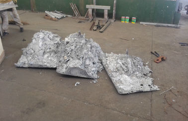
5.3.3 The workpiece will be move to flux tank after the acid tank, in the process of galvanizing, the flux in the regular inspection content, when the "iron" plating of ferrous ions in the liquid reaches the set value, start the remove iron from flux equipment to take out iron ion , and avoid excessive iron ion was taken in the liquid zinc , thereby reducing the consumption of zinc, after processing the flux liquid recycling.
5.3.4 After flux process, the workpiece through the closed automatic door of the acid closed room entering the galvanizing tank,dip into liquid zinc, start the fume treatment system, a large amount of dust in the galvanizing process through the flue suction zinc smoke treatment equipment, after collected by the dust collector is discharged to the atmosphere, solid particles in the exhaust gas is less than 90mg/m3, blackness reach first grade.( Fixed zinc smoke cover and zinc smoke treatment system are options)
5.3.5 Hot dip galvanizing is completed, a fixed zinc smoke cover's side and end doors open, workers put forward liquid zinc ash, after this , the workpieces will leave galvanizing tank, and then transferred to the cold water tank, then to passivation tank treatment, move to finish product area , trimmed and packed, thus completing the whole process of hot galvanizing.
6. Line details
6.1 Ring type crane : 6 sets of hoist
Hoist requirements: lifting weight: 2T, lift 10 meters, explosion-proof and ensure that the wire rope along the direction of walking in a plane. Two hoist for a group of remote control operation, each gourd each action can be operated separately, its operation and lifting speed must be synchronized.
6.2 Tank,
Steel structure tank
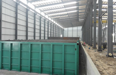
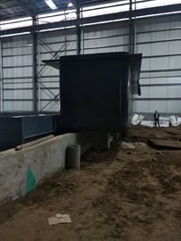
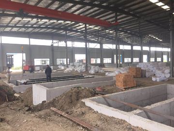
The tank is arranged in a large foundation pit, the foundation pit below the reinforced concrete masonry, FRP anti-corrosion treatment;
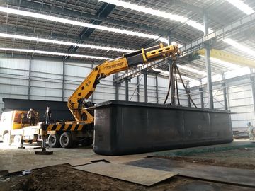
The tank structure: the welded steel structure frame and then welded steel tank for FRP anti-corrosion treatment in steel tank, the specific practice is: the wall is 10mm thick steel plate 25mm thick FRP processing, all external steel pool 4mm thick FRP do anti-corrosion processing.
6.3 Galvanizing tank heating system
6.3.1 Galvanizing tank:
7000×1200×2200mm, Thickness: 60mm,edge width:350mm, zinc weight :110ton,
tank weight : about 26ton
6.3.2 Zink tank heating system
6.3.2.1Technical parameters of furnace
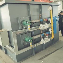
The system consists of heating furnace, burning system, control system and so on. Heating energy for Furnace heavy oil, automatic control of fuel flow, better control of the temperature in the furnace so that the temperature of zinc liquid more uniform stability.
6.3.2.1.1 Demension:
Galvanizing tank :7000×1200×2200mm(L×W×D)
Furnace body(rough):9000×3200×1800mm
6.3.2.1.2 Technical parameter
Zinc liquid working temperature (℃) 435-450 ±2;
Furnace (flue) temperature(℃) ≤650;
Furnace wall temperature (℃) ≤50;
Temperature fluctuation tolerance (℃):±2
Heating uniformity of furnace body (℃) :±2
Number of burners (unit) : 2units ,450KW/units,Consumption: 30 kg / hour
6.3.2.1.3 Others
All the explosion-proof lamps lighting tunnel
6.3.2.1.4 Technical performance
Production capacity: 20000 tons / year
Zinc capacity in the tank: 282 tons
Working temperature of zinc liquid :435-450 ℃
Furnace (fire tunnel) temperature :580 - 620℃
Full power temperature rising speed: 60 ~ 200 ℃/h , can be adjusted automatically according to setting curve
Smoke way: using a smoke exhaust fan, according to furnace pressure, AC frequency control speed.
6.3.2.2 Main parts of the furnace
6.3.2.2.1 Steel structure for the furnace
Including furnace shell, fire resistant cotton module, fire blankets, and other materials
6.3.2.2.2 Furnace structure:
The structure of the furnace side wall: the bottom of the furnace body and the inner cavity of the standard brick masonry, with 6mm thick steel plate welding furnace shell in structure, the cavity between the stove plate is filled glass fiber, the furnace shell is made of steel reinforcement.
Furnace structure: set the high speed burner at both ends of the unilateral diagonal arrangement of galvanizing tank, smoke extraction method using the bottom of the central smoke.
The pressure relief device is designed for the smoke tunnel and the furnace wall, which can quickly relieve the pressure of the furnace.
The galvanizing tank is supported by a steel structure pan to control the deformation .
Set the zinc leakage alarm device, and the zinc leakage collection pit.
6.3.2.2.3
Temperature control system
The temperature of the furnace is measured by the thermocouple and the setting temperature of the PLC (or temperature control meter) is compared with the PID operation of the temperature control meter (or PLC), and the corresponding pulse signal is output to control the air valve of each burner.
6.3.2.2.4
Air route design
The use of exhaust gas to heat the coming air, fuel costs can be reduced by 10%.
6.3.2.2.5
The structure of automatic control system for galvanizing furnace:
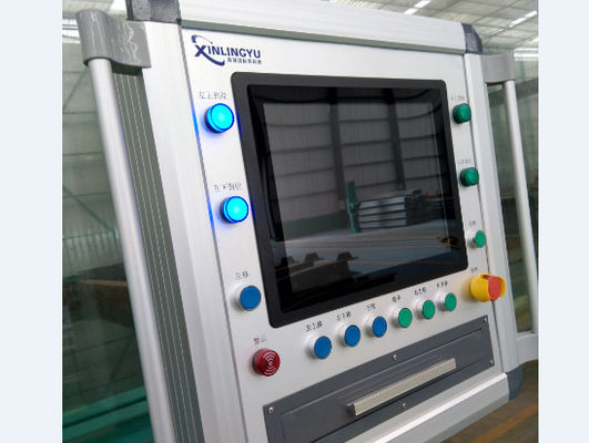
The basic automation system of the furnace includes two parts: instrument automation and electrical automation. It is composed of man-machine interface (HMI), PLC, field instrument, temperature controller, flow control valve and so on. The control system is divided into two modes: manual and automatic.
The stove is divided into 2 zones, two K type thermocouple, one is temperature control thermocouple, another is for the detection and comparison of this area; the galvanizing tank has two K type thermocouple to detect the temperature of zinc liquid.
the control function is to control the furnace temperature to get right temperature of zinc liquid, when the temperature of liquid zinc temperature close to the target temperature, the system automatically enters the cooling or warming state mode (automatic correction of furnace set temperature), the temperature of zinc liquid slowly close to the target temperature, effectively prevent the inertia effect of temperature. On the other hand, when the temperature of zinc liquid starts to drop, and the temperature is lower than certain temperature range, the system will automatically switch to the heating mode (the furnace temperature is automatically corrected) and repeat the above process. The whole control system is supplemented by furnace pressure control, fuel pressure and air pressure control.
6.4 Waste heat utilization:
Flux tank
The waste heat of the smoke of the galvanizing furnace is introduced into a waste heat exchanger. Through a titanium tube heat exchanger to heat the flux liquid, to keep the flux liquid temperature 60~70℃ automatically.
6.5 Post processing equipment
Cooling tower model: DBNL3-125
Tower size: Diameter: 3130mmx, height : 3540mm, 4kw
Tray glass fiber reinforced plastic material: φ4000mm * 800mm * wall thickness 8mm
6.6,Auxiliary equipment and facilities
6.6.1 Zinc dross machine (Option )
Quantity: 1 pieces , Height: 2.3m , capacity :1 ton
6.6.2Workshop power and lighting system
6.6.2.1, workshop power system
Install power box along the longitudinal side of workshop. See the "lighting system and power distribution system diagram of the galvanizing line"
6.6.2.2, workshop lighting system
Depending on the actual situation of construction site to determine the total plant, design capacity of about 10KW, divided into three line, Acid fume close room needs anti corrosion lamps and energy-saving light bulbs, other auxiliary room lighting by ceiling lamp, galvanizing tank pit lighting using incandescent lamp.
6.6.3 water supply and drainage system
Water supply:
Main pipe : φ63 PPR pipe,
Branch pipe: φ50 PPR pipe
under the floor , controlled by valves.
Drainage: waste water treatment system. After treatment, the neutral pump is used for production.
6.6.4 hanging beam, support and hanger
According to the specifications and the actual situation before the production by the user.
7. Environmental protection equipment
7.1 Pollution sources
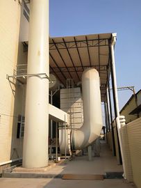
The pollution source of waste acid, acid fume, zinc smoke and dust, so environmental protection equipment from waste acid treatment system, acid fume treatment system, zinc smoke dust treatment system, this scheme introduces treatment of acid fume and zinc smoke.
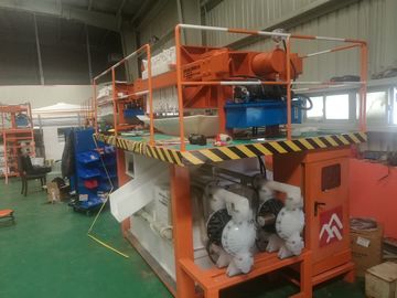
7.2 Flux regeneration system
On line regeneration treatment
The maximum regeneration processing capacity: 4m³/h
Flux PH: 3.0 - 4.5 pH
In Flux liquid , iron ions: less than 2g/l
Flux tank capacity: 50m³, pump: 1.5 inch, 400LPM flow (L / min), 12 ~ 15 hour for all one cycle.
Press and Filter machine : the filter area is ≥30m²
Dosing pump: peristaltic pump.
Reaction tank: 6-10 m³ plastic PP tank
7.3,Acid fume treatment system
7.3.2
Treatment effect
After treated by the two acid fume washing PP tank towers, the acid in the tail gas is less than 100mg/m3, the emission rate of less than 0.43kg/h, it can reach the standard of discharge by 20m high Chimney.
7.3.3 Design parameter:
Induced draft fan takes acid fume to treatment PP washing tank tower through pipe. According to the actual processing capacity of processing facilities, the line adopts 2 sets of washing tower by the way of connection series.
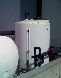
The washing tank tower series Description: the first tower use water spray, can be washed 80% acid fume and get dilute hydrochloric acid, used for cleaning process rack, the dilute hydrochloric acid and zinc on the process rack will generate zinc chloride, can be used for flux liquid; second tank tower with Alkaline liquid neutralization spraying, the remaining pickling in the discharge standard. This approach can greatly reduce the operation cost.
FRP centrifugal fan: Air volume: 25000m3/h, Wind pressure: 2400pa, Power: 22kw
Acid fume treatment PP washing tank tower
Parameters: the ratio of liquid to gas: 3.5 ~ 5.5L/m3;
the filler layer spacing: 1.1m;
the filler layer material:
Speed : 1.5m/s;
pressure loss range: ≤1.0 KPa
spiral cone type nozzle.
The bottom of the tower is provided with a circulating liquid tank, the liquid level is 1.2m;
an additional external water tank is 0.8 * 0.8 * 1.2m, which is convenient for adding alkali; the water tank is provided with a water inlet and an emptying opening.
Equipment dimension: diameter of 2500m * 8.3m
Material: FRP processing air volume: 25000m3/h
Empty tower wind speed: 1.5m/s, spray layer: 2 layers
Contact time: 10S total resistance of purification tower: 900Pa
Western ring (Bauer ring) packing height: 500mm (3 layers) gas-liquid ratio: 500:1
Circulating pump:
Model: pump 7.5HP flow: 40m3/h
Lift: 24m , power: 5.5kW x 2 units
7.4.4 Zinc smoke treatment
The workpiece into zinc tank after open fan, lead to the fume treatment system through the flue; the smoke collecting cover for the production of steel structure, to ensure that most of zinc smoke are collected which coming during workpieces dipping process, and through the pipeline into the flat bag dust collector, exhaust emission standard.
7.4.2Dust removal equipment
7.4.2.1 Smoke cover
According to the practical experience of the design and construction of the production line at home and abroad, a closed type zinc smoke collection system is adopted. The smoke cover on both sides of the observation window is arranged at the lower part of the lifting, convenient operation of the plating process, the observation window height of about 1.2 meters; the upper end of the closed cover installation of smoke dust absorbing channel. Induced draft fan keeps the negative pressure inside of cover, when the workpiece going to the zinc tank, closed at both ends of the electric door, smoke cannot escape that led to the fume treatment system by flue; the cover made of stainless steel shell body and steel frame, ensure the workpiece in the process of zinc dipping, most of zinc smoke are collected, and through the pipeline into spray treatment device. The collection rate is higher than 95%, and the exhaust gas meets the standard.
7.4.2.2 Zinc smoke treatment system
7.4.2.2.1Zinc smoke removal special equipment
Air handling capacity: 60000m3/h
Filter area: 1100㎡
Filter speed: 1.0m/min
resistance:1200-1500Pa
Negative pressure of equipment::5000Pa
7.4.2.2.2Modular combined dust collector

 Your message must be between 20-3,000 characters!
 Please check your E-mail!
  Your message must be between 20-3,000 characters!
 Please check your E-mail!
